

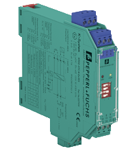
SMART Transmitter Power Supply KFD2-STC4-Ex1.ES
- 1-channel isolated barrier
- 24 V DC supply (Power Rail)
- Input for 2-wire SMART transmitters and current sources
- Output for 4 mA ... 20 mA or 1 V ... 5 V
- Sink or source mode
- Line fault detection (LFD)
- Up to SIL3 acc. to IEC 61508


Please note: All product-related documents, such as certificates, declarations of conformity, etc., which were issued prior to the conversion under the name Pepperl+Fuchs GmbH or Pepperl+Fuchs AG, also apply to Pepperl+Fuchs SE.
Utdrag ur datablad: Tekniska data för KFD2-STC4-Ex1.ES
| Product Description |
|---|
| Input 4 mA ... 20 mA Output 4 mA ... 20 mA |
| General specifications | ||
|---|---|---|
| Signal type | Analog input | |
| Functional safety related parameters | ||
| Safety Integrity Level (SIL) | SIL 3 | |
| Supply | ||
| Connection | Power Rail or terminals 14+, 15- | |
| Rated voltage | 19 ... 30 V DC | |
| Ripple | ≤ 10 % | |
| Rated current | ≤ 50 mA | |
| Power dissipation | ≤ 800 mW | |
| Power consumption | ≤ 1.2 W | |
| Input | ||
| Connection side | field side | |
| Connection | terminals 1+, 3-; 6+, 5- | |
| Input signal | 4 ... 20 mA , limited to approx. 27 mA reverse polarity protected | |
| Line fault detection | downscaling ≤ 3 mA ; upscaling ≥ 22 mA | |
| Voltage drop | approx. 5 V on terminals 5-, 6+ | |
| Available voltage | ≥ 15 V at 20 mA terminals 1+, 3- | |
| Output | ||
| Connection side | control side | |
| Connection | terminals 7-, 8+ | |
| Load | 0 ... 300 Ω (source mode) | |
| Output signal | 4 ... 20 mA or 1 ... 5 V (on 250 Ω, 0.1 % internal shunt) 4 ... 20 mA (sink mode), operating voltage 16 ... 28 V |
|
| Ripple | 20 mV rms | |
| Fault indication output | ||
| Output type | fault bus signal , open collector transistor | |
| Transfer characteristics | ||
| Deviation | at 20 °C (68 °F) ≤ ± 20 µA incl. calibration, linearity, hysteresis, loads and supply voltage fluctuations (source mode and sink mode 4 ... 20 mA) ≤ 10 mV incl. calibration, linearity, hysteresis and fluctuations of supply voltage (source mode 1 ... 5 V) |
|
| Influence of ambient temperature | < 2 µA/K (0 ... 70 °C (32 ... 158 °F)); < 4 µA/K (-20 ... 0 °C (-4 ... 32 °F)) (source mode and sink mode 4 ... 20 mA) < 0.5 mV/K (0 ... 70 °C (32 ... 158 °F)); < 1 mV/K (-20 ... 0 °C (-4 ... 32 °F)) (source mode 1 ... 5 V) |
|
| Frequency range | field side into the control side: bandwidth with 1 mApp signal 0 ... 3 kHz (-3 dB) control side into the field side: bandwidth with 0.5 Vpp signal 0 ... 3 kHz (-3 dB) |
|
| Settling time | ≤ 200 ms | |
| Rise time/fall time | ≤ 20 ms | |
| Galvanic isolation | ||
| Input/Output | safe electrical isolation acc. to IEC/EN 60079-11, voltage peak value 375 V | |
| Input/power supply | safe electrical isolation acc. to IEC/EN 60079-11, voltage peak value 375 V | |
| Output/power supply | Basic isolation acc. to EN 61010-1 rated insulation voltage ≤ 50 V | |
| Indicators/settings | ||
| Display elements | LEDs | |
| Control elements | DIP switch | |
| Configuration | via DIP switches | |
| Labeling | space for labeling at the front | |
| Directive conformity | ||
| Electromagnetic compatibility | ||
| Directive 2014/30/EU | EN 61326-1:2013 (industrial locations) | |
| Conformity | ||
| Electromagnetic compatibility | NE 21:2006 | |
| Degree of protection | IEC 60529:2001 | |
| Ambient conditions | ||
| Ambient temperature | -20 ... 70 °C (-4 ... 158 °F) | |
| Mechanical specifications | ||
| Degree of protection | IP20 | |
| Connection | screw terminals | |
| Mass | approx. 150 g | |
| Dimensions | 20 x 124 x 115 mm (0.8 x 4.9 x 4.5 inch) , housing type B2 | |
| Height | 124 mm | |
| Width | 20 mm | |
| Length | 115 mm | |
| Mounting | on 35 mm DIN mounting rail acc. to EN 60715:2001 | |
| Data for application in connection with hazardous areas | ||
| EU-type examination certificate | CESI 10 ATEX 076 | |
| Marking |  II (1)GD [Ex ia] IIC, [Ex iaD] [circuit(s) in zone 0/1/2/20/21/22] I (M1) [Ex ia] I II (1)GD [Ex ia] IIC, [Ex iaD] [circuit(s) in zone 0/1/2/20/21/22] I (M1) [Ex ia] I |
|
| Input | Ex ia, Ex iaD | |
| Supply | ||
| Maximum safe voltage | 253 V AC (Attention! Um is no rated voltage.) | |
| Equipment | terminals 1+, 3- | |
| Voltage | 25.2 V | |
| Current | 100 mA | |
| Power | 630 mW | |
| Internal capacitance | 5.7 nF | |
| Internal inductance | negligible | |
| Equipment | terminals 5-, 6+ | |
| Voltage | < 30 V | |
| Current | < 128 mA | |
| Voltage | 7.2 V | |
| Current | 100 mA | |
| Power | 25 mW | |
| Internal capacitance | 5.7 nF | |
| Internal inductance | negligible | |
| Certificate | PF 10 CERT 1750 X | |
| Marking | II 3G Ex nA II T4 |
|
| Directive conformity | ||
| Directive 2014/34/EU | EN 60079-0:2012+A11:2013 , EN 60079-11:2012 , EN 60079-15:2010 | |
| International approvals | ||
| UL approval | ||
| Control drawing | 116-0368 (cULus) | |
| IECEx approval | IECEx CES 11.0005 | |
| General information | ||
| Supplementary information | Observe the certificates, declarations of conformity, instruction manuals, and manuals where applicable. For information see www.pepperl-fuchs.com. | |
Classifications
| System | Classcode |
|---|---|
| ECLASS 13.0 | 27210119 |
| ECLASS 12.0 | 27210119 |
| ECLASS 11.0 | 27210119 |
| ECLASS 10.0.1 | 27210119 |
| ECLASS 9.0 | 27210119 |
| ECLASS 8.0 | 27210119 |
| ECLASS 5.1 | 27210119 |
| ETIM 9.0 | EC001485 |
| ETIM 8.0 | EC001485 |
| ETIM 7.0 | EC001485 |
| ETIM 6.0 | EC001485 |
| ETIM 5.0 | EC001485 |
| UNSPSC 12.1 | 32101514 |
Details: KFD2-STC4-Ex1.ES
Datasheet: KFD2-STC4-Ex1.ES
| Datasheet | File Type | File Size |
|---|---|---|
| Datasheet KFD2-STC4-Ex1.ES | 409 KB | |
| Fiche de données KFD2-STC4-Ex1.ES | 435 KB | |
| Datenblatt KFD2-STC4-Ex1.ES | 405 KB | |
| Datasheet KFD2-STC4-Ex1.ES | 438 KB | |
| Hoja de datos KFD2-STC4-Ex1.ES | 465 KB |
Documents: KFD2-STC4-Ex1.ES
| Manuals | File Type | File Size |
|---|---|---|
| Manual | 3685 KB | |
| Safety Manual | 427 KB | |
| Handbuch | 3693 KB | |
| Safety Manual | 2430 KB | |
| Instruction manuals | ||
| Инструкции | 69 KB | |
| Návod k poużití | 61 KB | |
| Instruktions manual | 58 KB | |
| Instruction manual | 50 KB | |
| Kasutusjuhend | 56 KB | |
| Käyttöohje | 56 KB | |
| Manuel d'instructions | 97 KB | |
| Betriebsanleitung | 62 KB | |
| Οδηγίες χρήσης | 73 KB | |
| Handleiding | 72 KB | |
| Instruction manual / Betriebsanleitung | 70 KB | |
| Használati útmutató | 71 KB | |
| Manuale di istruzioni | 93 KB | |
| Lietošanas pamācība | 68 KB | |
| Instrukciju vadovas | 68 KB | |
| Instrukcja obsługi | 72 KB | |
| Manual de instruções | 72 KB | |
| Manual de utilizare | 71 KB | |
| Návod na poużitie | 130 KB | |
| Manual de instrucciones | 95 KB | |
| Manual | 66 KB |
CAD+CAE: KFD2-STC4-Ex1.ES
| CAD | File Type | File Size |
|---|---|---|
| CAD 3-D / CAD 3-D | STP | 3048 KB |
Approvals+Certificates: KFD2-STC4-Ex1.ES
| Certificates | File Type | File Size |
|---|---|---|
| CESI IECEx Certificate of Conformity | LINK | --- |
| DNV Marine | 114 KB | |
| Europe CESI ATEX Category (1) GD ATEX Category (M1) | 803 KB | |
| Europe Pepperl+Fuchs Certificate of Compliance ATEX Category 3 | 201 KB | |
| TÜV SÜD Functional Safety Certificate | 188 KB | |
| USA Canada UL Hazardous Location Certificate of Compliance cULus UL E106378 | 413 KB | |
| Control Drawings | ||
| Control drawing UL / Control drawing UL | 397 KB | |
| Declaration of Conformity | ||
| EU Declaration of Conformity (P+F) / EU-Konformitäterklärung (P+F) | 54 KB |


Pepperl+Fuchs AB
Bultgatan 40 A
442 40 Kungälv
Sverige
orgnr. 556212-2126
info@se.pepperl-fuchs.com
 +46 303 246070
Pepperl+Fuchs is a leading developer and manufacturer of electronic sensors and components for the global automation market. Continuous innovation, enduring quality, and steady growth have been the foundation of our success for more than 70 years. Pepperl+Fuchs employs 6,300 people worldwide and has manufacturing facilities in Germany, USA, Singapore, Hungary, Indonesia and Vietnam, most of them ISO 9001 certified.